A clearer view of
your cold room.
Meet the next generation of Airflow control-panel layouts. Custom touchscreen operation, animated system views, and a deeper look at the health of your refrigeration equipment—designed in-house around your facility.
Preview only. These new control-panel layouts are not yet available for purchase. Features and release timing are still being finalized.
MORE THAN A TEMPERATURE DISPLAY
See the room.
Understand the system.
Critical environments need more than a single reading. Our upcoming controls bring room conditions, refrigeration performance, electrical measurements, operating sequences, and service information into a coordinated view.
Monitoring superheat, subcooling, amperage, and other operating indicators can help technicians spot changes early and keep equipment within its intended operating conditions. Paired with proper maintenance and a timely response, that can support longer equipment life and help reduce unexpected downtime for research, products, and processes that matter.
Built for your application
Cold rooms, freezers, and environmental chambers, with the hardware, sensors, and sequences selected for the conditions your operation requires.
Designed in-house
Airflow designs, builds, and programs the control solution around your project, using Watlow RMC control hardware and Maple Systems touchscreens.
Recognizably yours
Your company logo, colors, photographs, room diagrams, equipment labels, and screen layout. A familiar interface for the people who use it every day.
ACTUAL EASYBUILDER OFFLINE SCREENS
The real layouts.
Up close.
Browse direct screenshots from our Airflow EasyBuilder offline simulator. These are the actual screen graphics and layouts from the native project. Animated components are shown as still captures here.
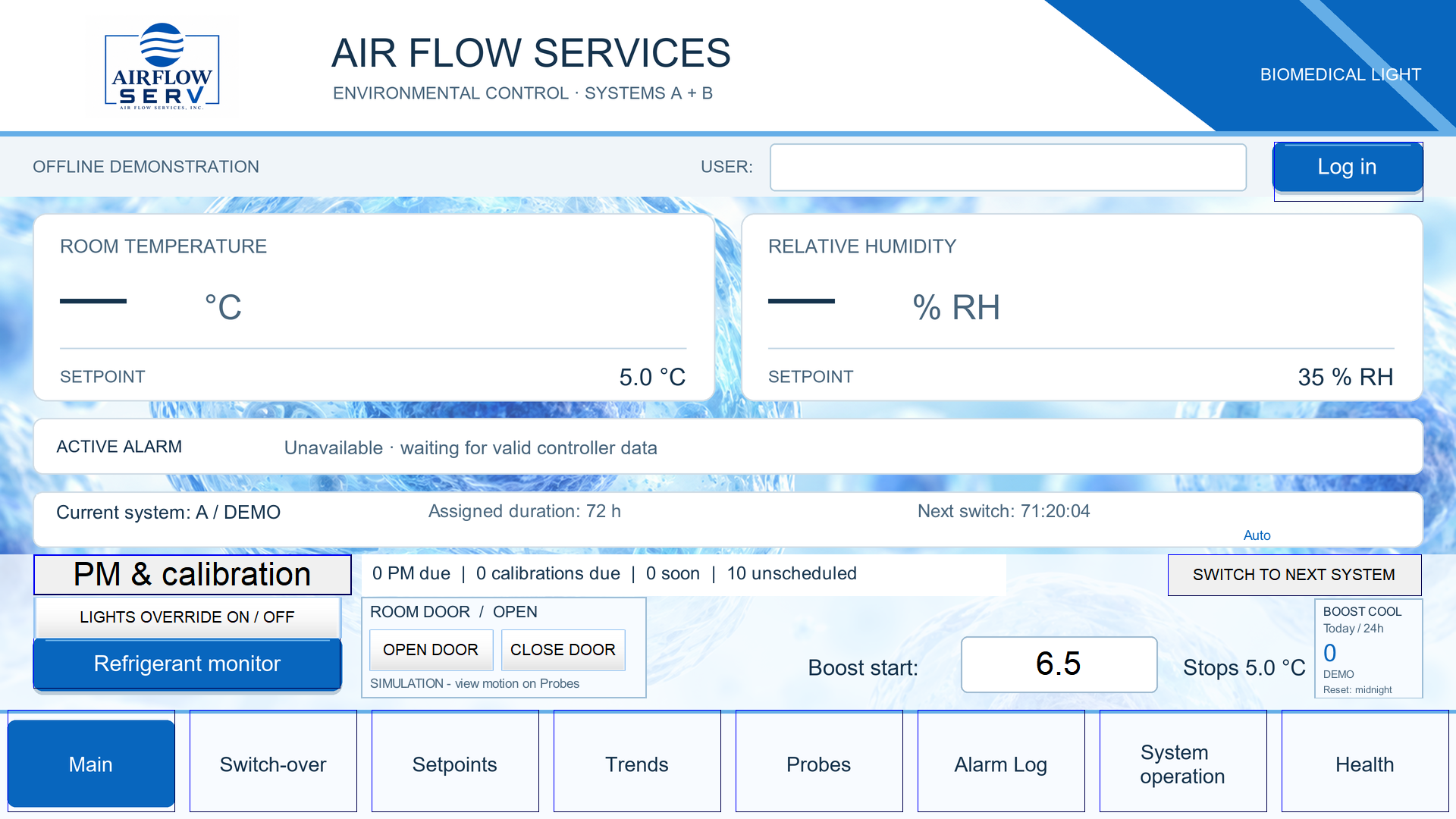
Room conditions at a glance
The actual Airflow main screen, with temperature and humidity setpoints, system status, room-door controls, lighting, and maintenance reminders. Live readings are intentionally unavailable in this offline capture.
Open full-size screenshot ↗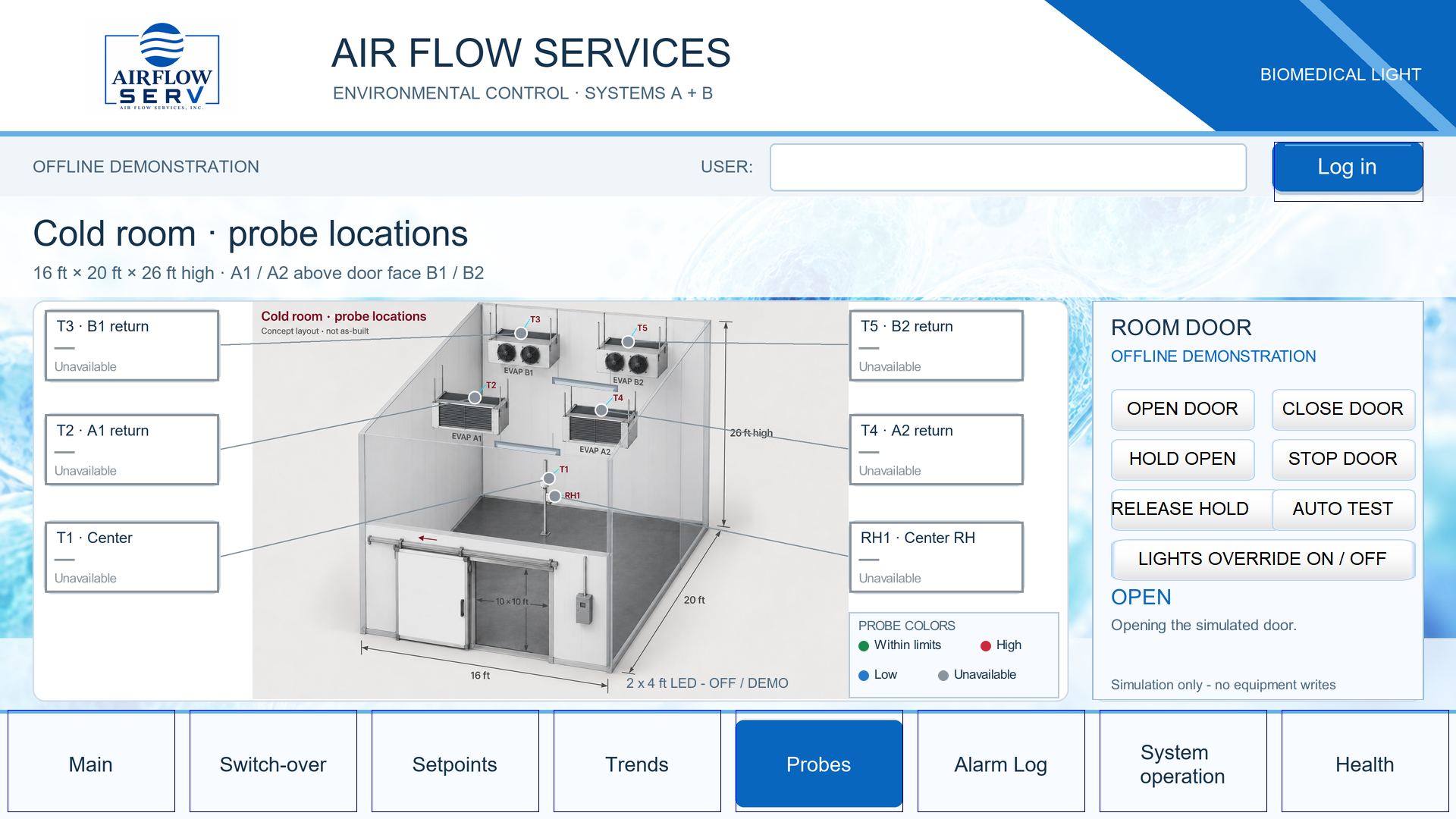
Connect the reading to the room
The actual probe-location screen with the room illustration, sensor locations, door controls, and lighting controls. This capture shows the simulated door open.
Open full-size screenshot ↗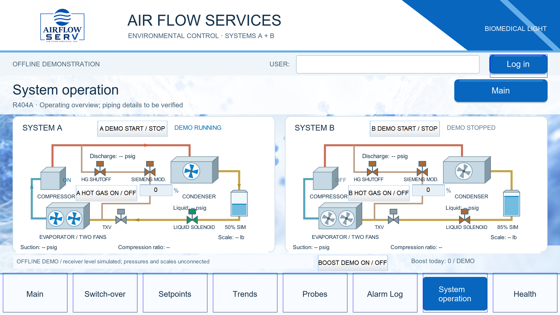
See both refrigeration systems
The actual operating screen with independent A/B system controls, fans, valves, refrigerant paths, hot-gas controls, and illustrative receiver levels. System A is running in this offline capture.
Open full-size screenshot ↗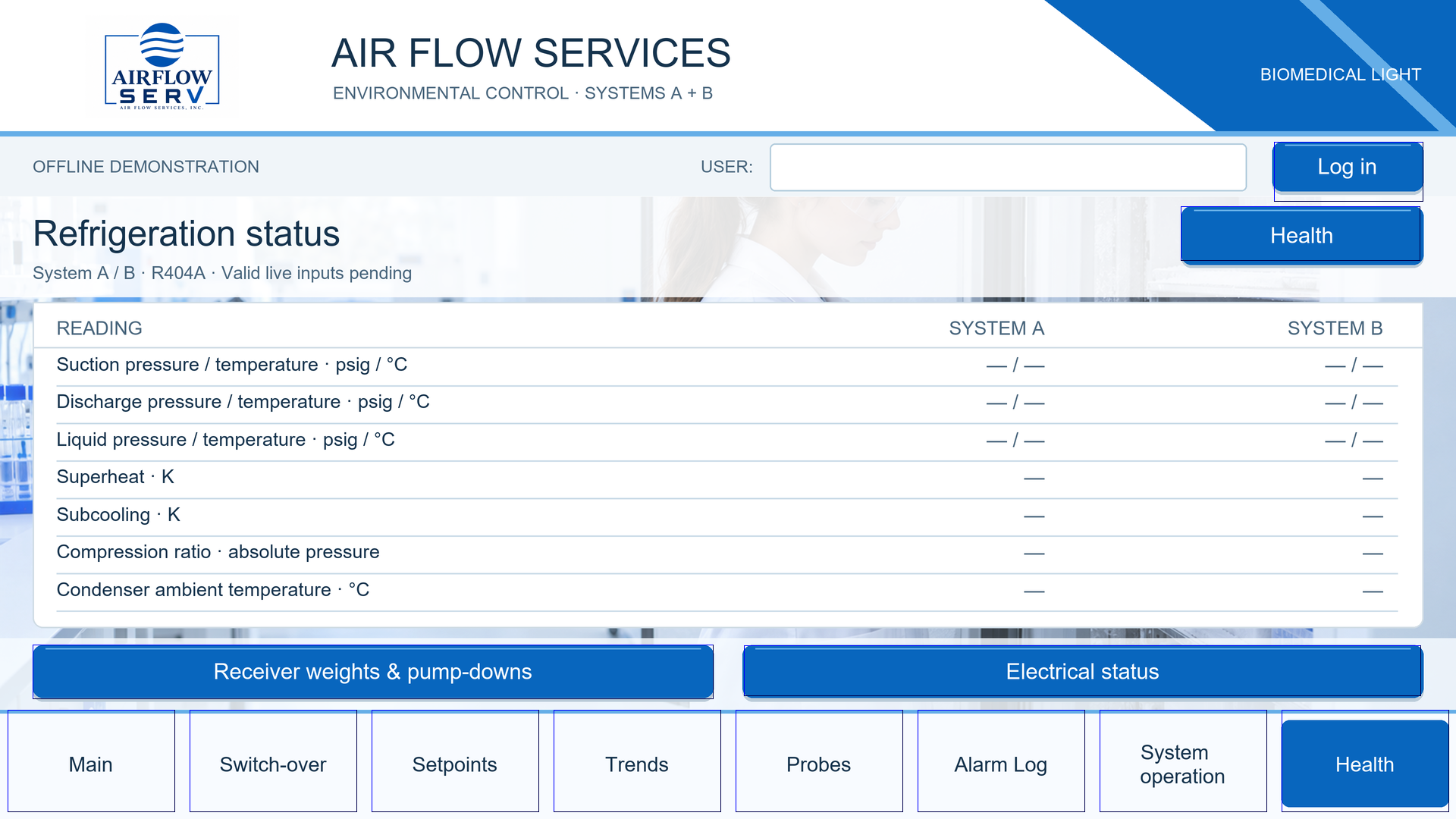
Look beyond room temperature
The actual refrigeration-status screen: suction, discharge, and liquid pressure and temperature, superheat, subcooling, compression ratio, and condenser ambient temperature. Live sensor integration is pending.
Open full-size screenshot ↗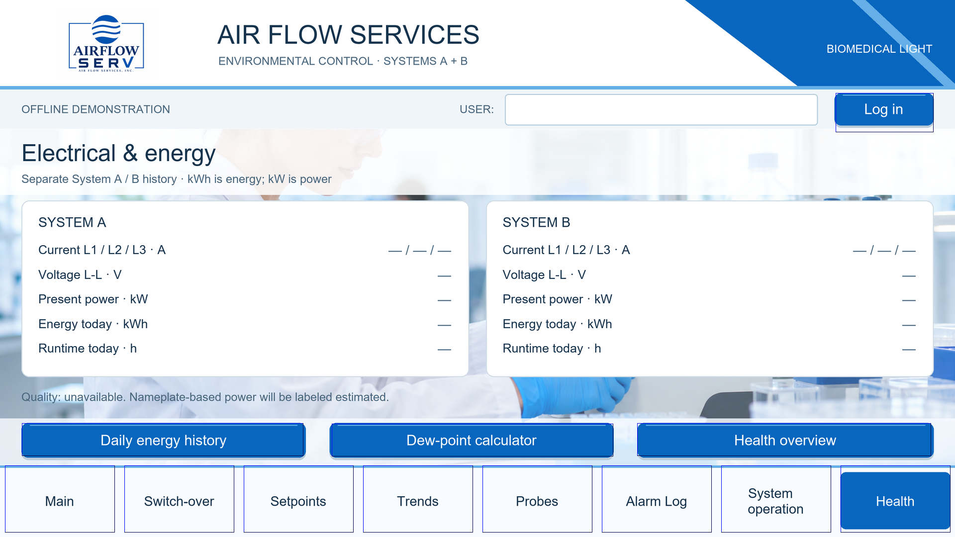
Understand the electrical picture
The actual electrical screen includes phase currents, line-to-line voltage, power, energy, and runtime for both systems. Values require the specified sensors, metering, and data integration.
Open full-size screenshot ↗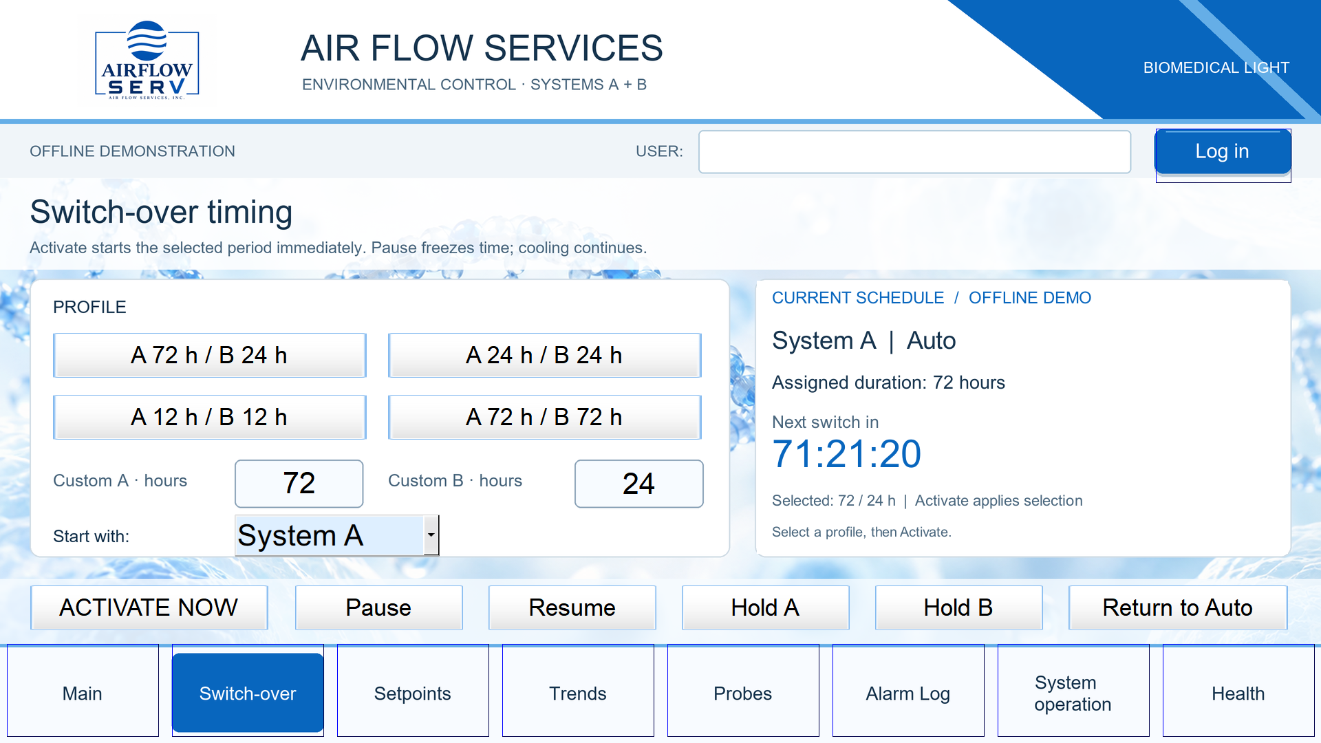
Plan the operating schedule
The actual changeover screen offers timing profiles, custom A/B durations, starting-system selection, hold modes, and automatic rotation. The offline timer is running in this capture.
Open full-size screenshot ↗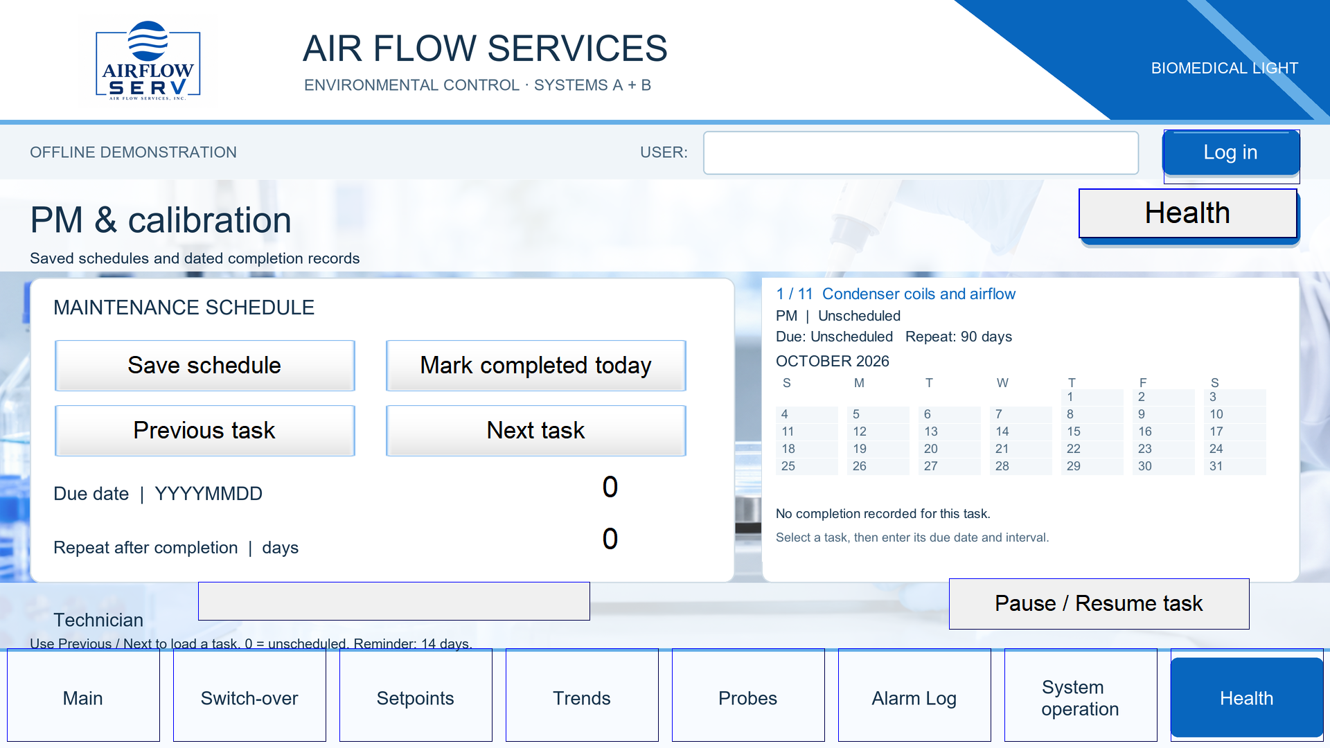
Keep routine care visible
The actual maintenance-and-calibration screen with task selection, due dates, repeat intervals, completion information, and pause/resume controls. Production retention and integration are still being finalized.
Open full-size screenshot ↗Choose a screen above; select the image to view it full size. Keyboard users can tab to the screen choices and use the arrow keys. These are screenshots of the native offline simulator, not active equipment controls.
THE MONITORING PACKAGE
Look beyond the setpoint.
We are developing a configurable health-monitoring approach that brings the room and its refrigeration equipment into the same picture. The sensor package is selected for your system—not a fixed bundle of readings that every room must have.
Electrical health
Multiple voltage-monitoring points and current probes for compressors, motors, and other selected loads. Review phase currents, voltage conditions, operating proof, and—with the appropriate metering—power, energy use, and runtime.
Refrigeration performance
Pressure transducers and matched line-temperature sensors provide a basis for suction, discharge, and liquid-line views, superheat, subcooling, and compression-ratio calculations where applicable.
Room and equipment sensing
Thermistors, RTDs, and other temperature probes; humidity sensors; ambient measurements; and project-specific probe maps help connect a reading to its physical location.
Dual-system operation
System A/B status, scheduled lead/lag changeover, hold modes, boost-cooling sequences, and animated operating views. The capacity and backup strategy are defined for your application.
Alarms, trends, and service
Clear alarm messages, acknowledgement and event-history views, selected operating trends, diagnostic screens, and technician information. Recorded values and retention are defined during design.
Maintenance and calibration
Task reminders, editable schedules, calibration due dates, and completion information. Keep routine care visible alongside day-to-day operation.
Door and lighting functions
Room-door status and control views, lighting overrides, timed lighting, and occupancy-based options where supported by the installed hardware and agreed control sequence.
Additional system insight
Receiver-scale inputs, pump-down views, condenser ambient conditions, dew-point information, and hot-gas control displays can be considered where relevant and instrumented.
Your workflow and identity
Company logos, color schemes, room photographs, equipment illustrations, naming conventions, and screen organization tailored to your team. Operator and technician access can be configured by role.
The new layouts and monitoring package are in development. Final hardware, sensor mapping, calculations, alarms, records, and control sequences must be selected and verified for each project. Monitoring supports maintenance decisions; it does not guarantee fault prevention, equipment life, or uninterrupted operation.
CUSTOMIZED FOR YOUR FACILITY
Your identity.
Your workflow.
The Airflow branding in these screenshots is an example. We can build your company identity and project details into the actual control screens.
- Your logo and company name
Make the control system feel at home in your facility. - Your colors, photos, and graphics
Coordinate the screen design with your brand while keeping status and alarm information clear. - Your rooms and equipment
Use project-specific room illustrations, probe locations, equipment labels, and operating views. - Your team's workflow
Organize screens, navigation, operator access, and technician information around how you work.
PLANNED DISPLAY OPTIONS
The right screen
for the way you work.
Planned touchscreen options include 7-inch, 10-inch, and 15½-inch displays, with screen layouts adapted for the selected size. We will help match the display, enclosure, and controls to your equipment and operator needs.
Planned offerings; final model selection and availability will be confirmed when the new layouts are released.
COMING SOON · REGISTER YOUR INTEREST
Imagine this
in your facility.
Tell us about your room, equipment, monitoring priorities, and branding ideas. We welcome early conversations while development continues.
Email your interestNo orders or deposits are being taken for these new layouts.